Wiring the motor driver, encoder and CAN module straight to the Nucleo for the pan tracker got messy fast, and finding the right pin on the Zio headers every time was a pain. There’s only one 3V3 socket on the Zio headers too (CN8-7).
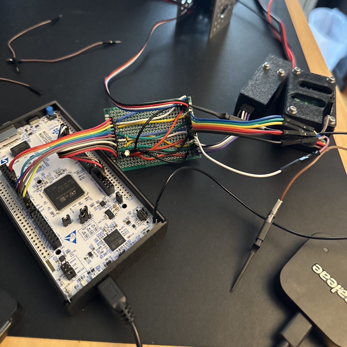
I got frustrated and wired out a proto board as a hub. A common thread between posts here: spatial organization is important to me! I can’t stand wire clutter and fragile hardware setups. I digress.
One column of pins jumpers to the Nucleo, with one header per device on the other side (CAN transceiver, motor driver, encoder). One signal per row, 3V3 and GND buses, and Saleae test pins on every signal. The motor driver’s ENA/ENB tie, the current sense filter and a 3V3 bypass cap live on the hub too.
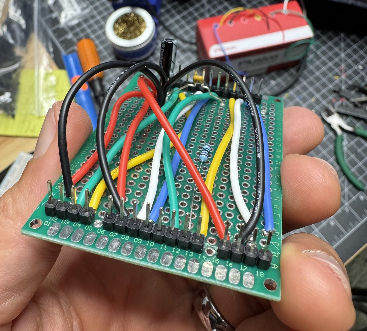
I was quite pleased with the result for about 2 days, then the scope grew. I realized that the tracker needs a homing sensor so it knows where zero is, and once there’s a homing sensor, end-of-travel sensors and an e-stop aren’t far behind. Another proto board didn’t make sense at that point (I’m tired of inhaling solder fumes), so I designed a custom shield with Claude: I set the requirements and checked its work, and it did the KiCad grunt work (quite well, might I add).
Background
- Shield
- A board that plugs straight onto the dev board’s headers.
- Zio connectors
- The NUCLEO-144’s headers: the Arduino Uno rows, plus a second row one column inward.
- Shunt
- A small jumper cap that connects two neighboring header pins.
- Diode-OR
- Several signals, each through its own diode, into one node, so any of them can pull it high.
- BOM and CPL
- The assembly files: the parts list, and the position and rotation of every part.
The board
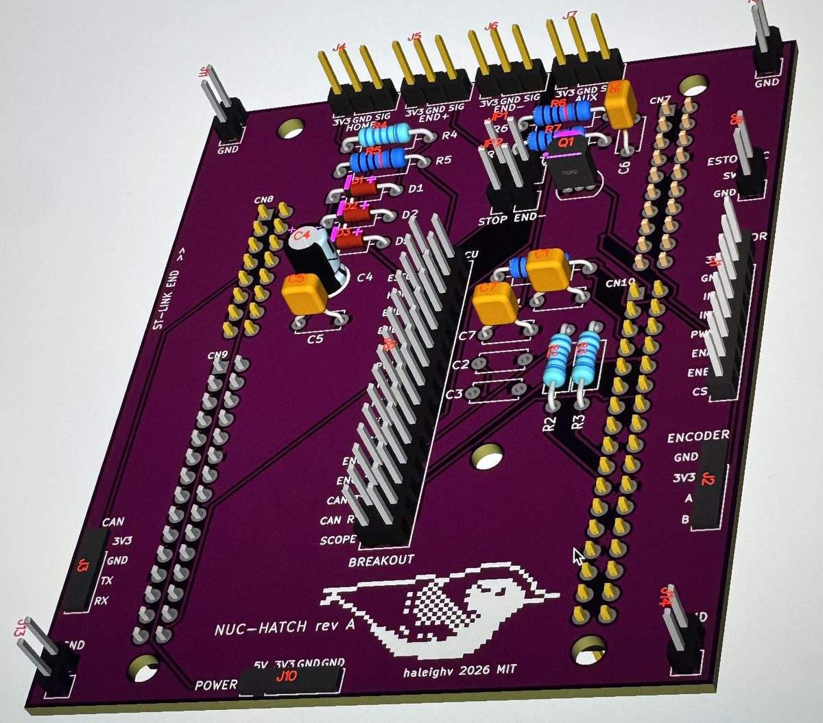
- Headers for the CAN module, the VNH5019 and the encoder, HOME / END+ / END- / AUX sensor inputs, a normally closed e-stop, power, and a probe ground in each corner.
- New pins: HOME on PD14 (TIM4 CH3, input capture for homing), AUX on PD15 (TIM4 CH4), END+ on PF3, END- on PG1, ESTOP on PG12.
- A 2x15 breakout down the middle. Each signal has its device side on one row and its MCU side on the other, joined by a shunt. Pull a shunt to cut a device off and probe either side.
- Hardware stop: the e-stop (open, or a broken wire) and the end sensors (through JP1/JP2) are diode-ORed into a 2N3904 that pulls EN low. The VNH5019 turns off without the firmware, and the firmware sees EN low as the motor fault it already handles. It sits on the device side of the breakout, so it still works with the shunts pulled.
- 2 layers, all through-hole, GND pour on both sides.
Getting it to fit
- Knowing that the Nucleo’s mounting holes are the Arduino Uno holes, I had Claude start from KiCad’s Arduino Uno footprint (plus the second row).
- Claude checked all 27 Zio pins in use against UM2407 tables 18-21, then generated a 1:1 image. I printed the paper render of the board at 1:1 and pushed the paper onto the Nucleo to make sure every pin lined up.
- The parts, nets and placement live in a Python spec that generates the schematic, placement and BOM. Claude couldn’t drive KiCad, so I ran Freerouting and DRC myself and cleaned up the routing in KiCad 10. ERC clean, DRC 0 with 7 exclusions (courtyards around the Nucleo’s mounting holes, same as on the Nucleo itself).
The logo
It’s called Nuc-hatch (Nuc[leo] Hatch…) so of course the silkscreen gets a nuthatch! Converted a favorite image of mine to pixel art: 1-bit at 0.5 mm per pixel.

Ordering
Ordering an assembled board was a new experience for me - I’ve always fabbed bare boards and populated them myself. Details:
- JLCPCB: 5 boards, purple, lead-free HASL, assembled on both sides (the Zio headers go on the bottom to mate with the Nucleo, hence “shield”)
- $58.77 for boards, parts and assembly, and $143.78 total with UPS DDP shipping, duties and taxes. Global Standard shipping was about $80, but it leaves the duties to be billed at delivery! I was stoked with the price until we got to shipping…
- Assembly needs an LCSC part number on every line. Through-hole parts are all “Extended”, and a few weren’t in stock: the 1N4148 moved to C84410, and the 1x2, 2x15 and 2x17 headers came from other makers. Claude helped a lot with finding these part numbers.
- JLCPCB’s header 3D models sit 90° off from KiCad’s, so the placement file turns every header 270° to compensate!
Next
Looking forward to bring-up when the boards arrive! I’ll do a continuity and shorts check on the bare board, then 3V3 and 5V with no Nucleo, then on the Nucleo with every shunt pulled, then one signal at a time. After that, another round of rewiring and hardware validation testing.